


#10weekcloudops
Introduction:
The two-tier architecture is a common design pattern for deploying web applications that separate the front-end and back-end components into distinct tiers or layers. In this architecture, the front-end tier typically consists of web servers or instances that handle user requests, while the back-end tier includes a database or data storage layer.
When deploying a two-tier architecture on AWS using Terraform, you can leverage various AWS services such as EC2, RDS, and VPC. Here’s an overview of the deployment process:
VPC Configuration: Begin by defining the Virtual Private Cloud (VPC) for your architecture. The VPC provides isolated network space for your resources.
Subnet Configuration: Create subnets within the VPC to segregate your resources. Typically, you will have a public subnet for front-end instances and a private subnet for the back-end database.
Security Group Configuration: Define security groups to control inbound and outbound traffic to your instances. Ensure that the appropriate ports are open for web traffic (e.g., HTTP, HTTPS) to the front-end instances.
EC2 Instance Configuration: Use the
aws_instanceresource in Terraform to provision EC2 instances in the public subnet. These instances will serve as the front-end web servers or application servers for your web application.RDS Configuration: Define an RDS instance using the
aws_db_instanceresource in Terraform. This will provide the database for your back-end tier. Specify the necessary configurations, such as engine type, instance size, and database credentials.Subnet Group Configuration: Create a DB subnet group using the
aws_db_subnet_groupresource to associate the RDS instance with the private subnet. This ensures that the database is securely isolated within the private subnet.Load Balancer Configuration: To enhance scalability and availability, consider using an Application Load Balancer (ALB) or Network Load Balancer (NLB) in front of the EC2 instances. Configure the load balancer to distribute traffic evenly among the instances.
Deployment: Finally, run
terraform initto initialize your Terraform configuration, followed byterraform applycreating and provisioning the resources defined in your Terraform code.
Github repo: https://github.com/HARSHALJETHWA19/2-tier-web-architecture
Steps to Create AWS Two-Tier Architecture Deployment With Terraform
Step 1: Initiate Working Directory and Provider Configurations
In the IDE, create a new working directory and change into that directory with this syntax:
mkdir <directory name>
cd <directory name>
In the new working directory, create a main.tf file to begin writing our cloud infrastructure:
touch main.tf
then, open the main.tf file and write down the below code:
terraform {
  required_providers {
    aws = {
      source  = "hashicorp/aws"
      version = "~> 4.0"
    }
  }
}

# Configure AWS Provider
provider "aws" {
  region = "us-east-1"
}
Step 2: Declare VPC and Internet Gateway Resources
With the previous step, declare the VPC and attached Internet Gateway for the infrastructure:
# Deploy VPC
resource "aws_vpc" "vpc" {
  cidr_block       = "10.0.0.0/16"
  instance_tenancy = "default"

  tags = {
    Name = "2-tier-web-architecture"
  }
}

# Deploy Internet Gateway
resource "aws_internet_gateway" "ig" {
  vpc_id = aws_vpc.vpc.id

  tags = {
    Name = "2-tier-web-vpc"
  }
}
Step 3 — Enable Public and Private Subnets
declare both the public and private subnets in the infrastructure with the following syntax:
# Deploy 2 Public Subnets
resource "aws_subnet" "public1" {
  vpc_id                  = aws_vpc.vpc.id
  cidr_block              = "10.0.1.0/24"
  availability_zone       = "us-east-1a"
  map_public_ip_on_launch = true

  tags = {
    Name = "1public"
  }
}

resource "aws_subnet" "public2" {
  vpc_id                  = aws_vpc.vpc.id
  cidr_block              = "10.0.2.0/24"
  availability_zone       = "us-east-1b"
  map_public_ip_on_launch = true

  tags = {
    Name = "2public"
  }
}

# Deploy 2 Private Subnets
resource "aws_subnet" "private1" {
  vpc_id                  = aws_vpc.vpc.id
  cidr_block              = "10.0.3.0/24"
  availability_zone       = "us-east-1a"
  map_public_ip_on_launch = false

  tags = {
    Name = "1private"
  }
}

resource "aws_subnet" "private2" {
  vpc_id                  = aws_vpc.vpc.id
  cidr_block              = "10.0.4.0/24"
  availability_zone       = "us-east-1b"
  map_public_ip_on_launch = false

  tags = {
    Name = "2private"
  }
}
Step 4 — Set Route Table and Subnet Associations
The following syntax will declare the route table and its subnet associations for the infrastructure:
# Deploy Route Table
resource "aws_route_table" "rt" {
  vpc_id = aws_vpc.vpc.id

  route {
    cidr_block = "0.0.0.0/0"
    gateway_id = aws_internet_gateway.ig.id
  }
  tags = {
    Name = "routetable"
  }
}

# Associate Subnets With Route Table
resource "aws_route_table_association" "route1" {
  subnet_id      = aws_subnet.public1.id
  route_table_id = aws_route_table.rt.id
}

resource "aws_route_table_association" "route2" {
  subnet_id      = aws_subnet.public2.id
  route_table_id = aws_route_table.rt.id
}
Step 5 — Configure Security Groups
The following provides the HCL syntax to properly declare these critical pieces of the infrastructure:
# Deploy Security Groups
resource "aws_security_group" "publicsg" {
  name        = "publicsg"
  description = "Allow traffic"
  vpc_id      = aws_vpc.vpc.id

  ingress {
    from_port   = 80
    to_port     = 80
    protocol    = "tcp"
    cidr_blocks = ["0.0.0.0/0"]
  }
  ingress {
    from_port   = 22
    to_port     = 22
    protocol    = "tcp"
    cidr_blocks = ["0.0.0.0/0"]
  }
  egress {
    from_port   = 0
    to_port     = 0
    protocol    = "-1"
    cidr_blocks = ["0.0.0.0/0"]

  }
}

resource "aws_security_group" "privatesg" {
  name        = "privatesg"
  description = "Allow traffic"
  vpc_id      = aws_vpc.vpc.id

  ingress {
    from_port       = 3306
    to_port         = 3306
    protocol        = "tcp"
    cidr_blocks     = ["10.0.0.0/16"]
    security_groups = [aws_security_group.publicsg.id]
  }
  ingress {
    from_port   = 22
    to_port     = 22
    protocol    = "tcp"
    cidr_blocks = ["0.0.0.0/0"]
  }
  egress {
    from_port   = 0
    to_port     = 0
    protocol    = "-1"
    cidr_blocks = ["0.0.0.0/0"]

  }
}

# Deploy ALB Security Group
resource "aws_security_group" "albsg" {
  name        = "albsg"
  description = "ALB Security Group"
  vpc_id      = aws_vpc.vpc.id

  ingress {
    from_port   = "0"
    to_port     = "0"
    protocol    = "-1"
    cidr_blocks = ["0.0.0.0/0"]
  }
  egress {
    from_port   = "0"
    to_port     = "0"
    protocol    = "-1"
    cidr_blocks = ["0.0.0.0/0"]
  }
}
Step 6 — Configure the Application Load Balancer
# Deploy Application Load Balancer
resource "aws_lb" "alb" {
  name               = "alb"
  internal           = false
  load_balancer_type = "application"
  security_groups    = [aws_security_group.albsg.id]
  subnets            = [aws_subnet.public1.id, aws_subnet.public2.id]
}

# Create ALB Target Group
resource "aws_lb_target_group" "albtg" {
  name     = "albtg"
  port     = 80
  protocol = "HTTP"
  vpc_id   = aws_vpc.vpc.id

  depends_on = [aws_vpc.vpc]
}

# Deploy LB Target Attachments
resource "aws_lb_target_group_attachment" "tgattach1" {
  target_group_arn = aws_lb_target_group.albtg.arn
  target_id        = aws_instance.instance1.id
  port             = 80

  depends_on = [aws_instance.instance1]
}

resource "aws_lb_target_group_attachment" "tgattach2" {
  target_group_arn = aws_lb_target_group.albtg.arn
  target_id        = aws_instance.instance2.id
  port             = 80

  depends_on = [aws_instance.instance2]
}

# Deploy LB Listener
resource "aws_lb_listener" "lblisten" {
  load_balancer_arn = aws_lb.alb.arn
  port              = "80"
  protocol          = "HTTP"

  default_action {
    type             = "forward"
    target_group_arn = aws_lb_target_group.albtg.arn
  }
}
Step 7 — Set Up EC2 Instance
write below in the previous HCL code. it will create an EC2 instance with bootstrapping:
# Deploy EC2 Instances
resource "aws_instance" "instance1" {
  ami                         = "ami-0b0dcb5067f052a63"
  instance_type               = "t2.micro"
  availability_zone           = "us-east-1a"
  vpc_security_group_ids      = [aws_security_group.publicsg.id]
  subnet_id                   = aws_subnet.public1.id
  associate_public_ip_address = true
  user_data                   = <<-EOF
        #!/bin/bash
        yum update -y
        yum install httpd -y
        systemctl start httpd
        systemctl enable httpd
        echo "<html><body><h1>First instance successfully deployed</h1></body></html>" > /var/www/html/index.html
        EOF

  tags = {
    Name = "ec2instance1"
  }
}
resource "aws_instance" "instance2" {
  ami                         = "ami-0b0dcb5067f052a63"
  instance_type               = "t2.micro"
  availability_zone           = "us-east-1b"
  vpc_security_group_ids      = [aws_security_group.publicsg.id]
  subnet_id                   = aws_subnet.public2.id
  associate_public_ip_address = true
  user_data                   = <<-EOF
        #!/bin/bash
        yum update -y
        yum install httpd -y
        systemctl start httpd
        systemctl enable httpd
        echo "<html><body><h1>Second instance successfully deployed</h1></body></html>" > /var/www/html/index.html
        EOF

  tags = {
    Name = "ec2instance2"
  }
}
Step 8 — Configure RDS in Private Subnets
We will finalize our data tier with the following syntax:
# Relational Database Service Subnet Group
resource "aws_db_subnet_group" "dbsubnet" {
  name       = "dbsubnet"
  subnet_ids = [aws_subnet.private1.id, aws_subnet.private2.id]
}

# Create RDS Instance
resource "aws_db_instance" "dbinstance" {
  allocated_storage      = 5
  engine                 = "mysql"
  engine_version         = "5.7"
  instance_class         = "db.t2.micro"
  identifier             = "dbinstance"
  db_name                = "db"
  username               = "admin"
  password               = "password"
  db_subnet_group_name   = aws_db_subnet_group.dbsubnet.id
  vpc_security_group_ids = [aws_security_group.privatesg.id]
  skip_final_snapshot    = true
}
Step 9 — Create Outputs. tf file
Initiate the creation of the outputs.tf file with the following syntax:
touch outputs.tf
then, write the following syntax:
# Outputs
# Show EC2 Instance Public IPv4 Address
output "ec2publicip" {
  value = aws_instance.instance1.public_ip
}

# Show DB Instance Address
output "dbinstanceaddress" {
  value = aws_db_instance.dbinstance.address
}

# Show DNS of LB
output "lb_dns_name" {
  description = "The DNS of LB"
  value       = aws_lb.alb.dns_name
}
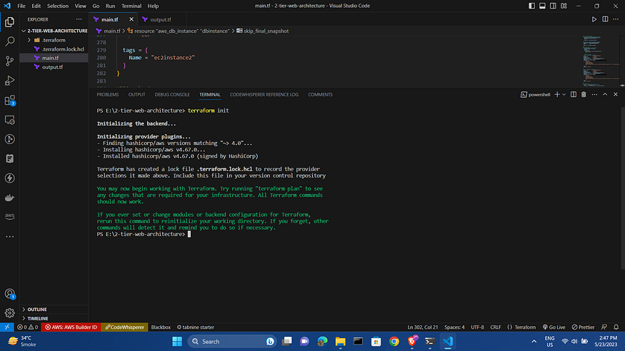
Step 10 — Initialize Terraform
With our .tf files populated with HCL to manage our infrastructure and outputs, we need to initialize Terraform with the following command:
terraform init
will return similar output:
We can further organize and clean our Terraform source code files with the following command:
terraform fmt
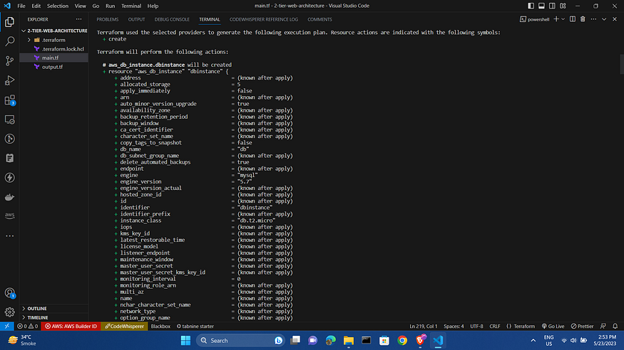
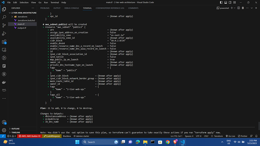
Step 11 — Plan and Apply
With our code formatted properly, we can execute the plan and apply phases of the workflow:
terraform plan
With proper deployment plans verified, we will insert the following command to apply and build out the infrastructure:
terraform apply
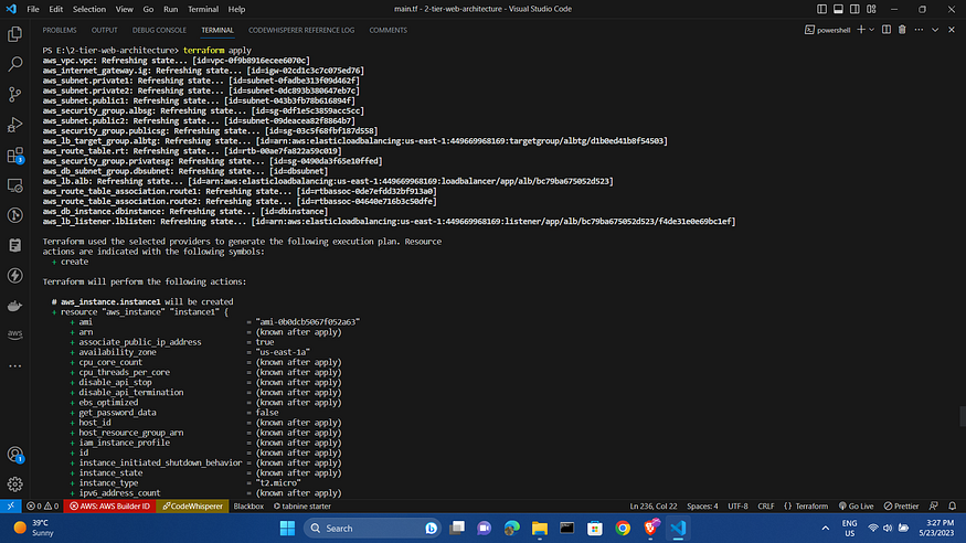
After the apply the AWS console resources will be :
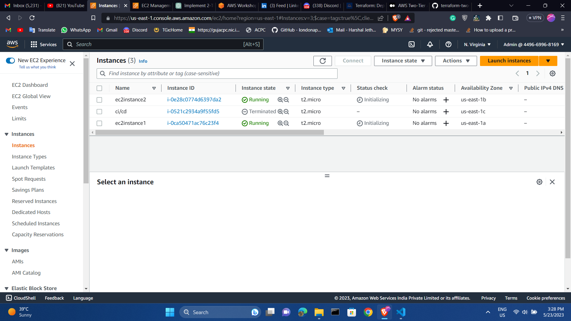
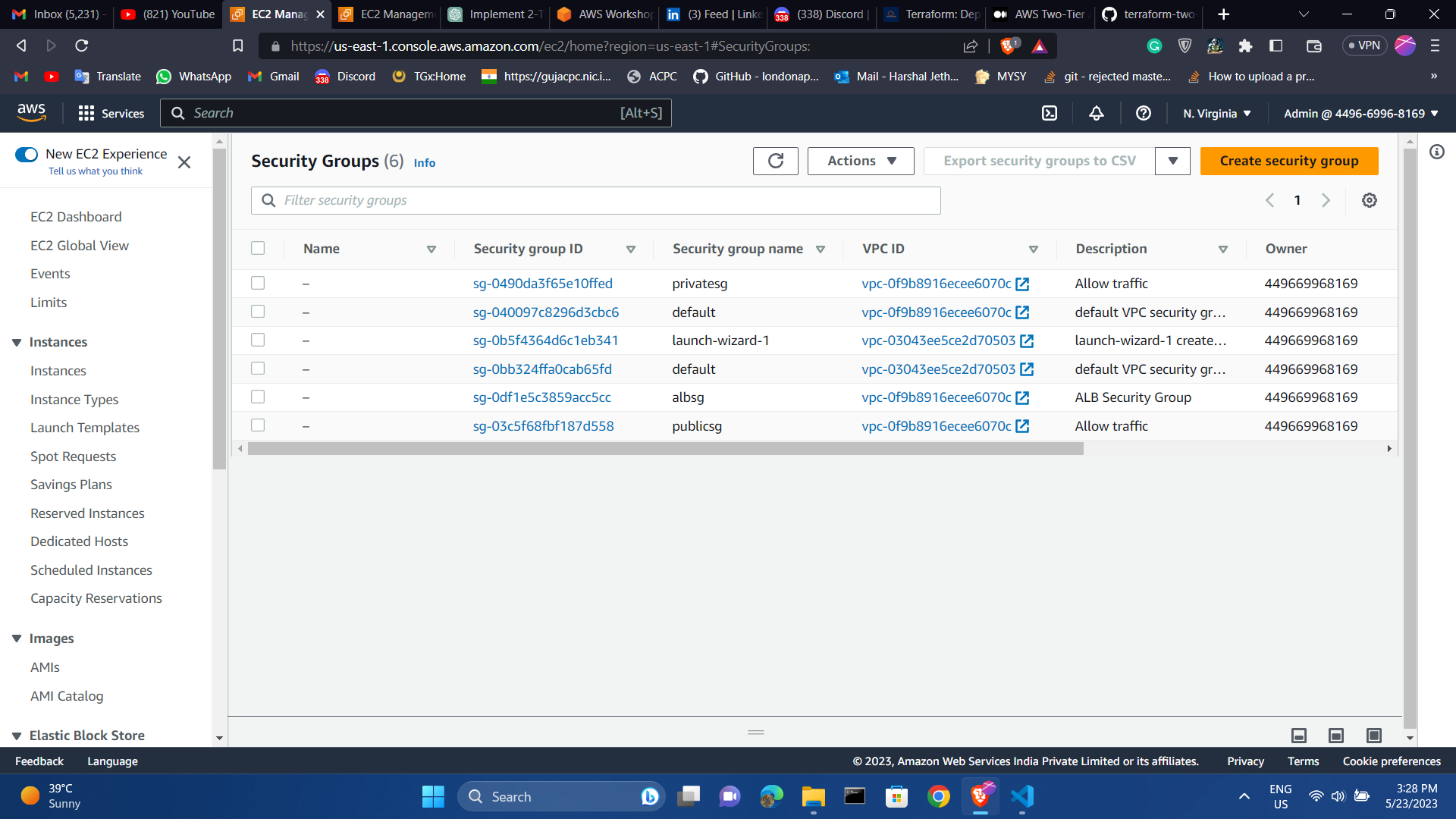
Ec2 and security group list
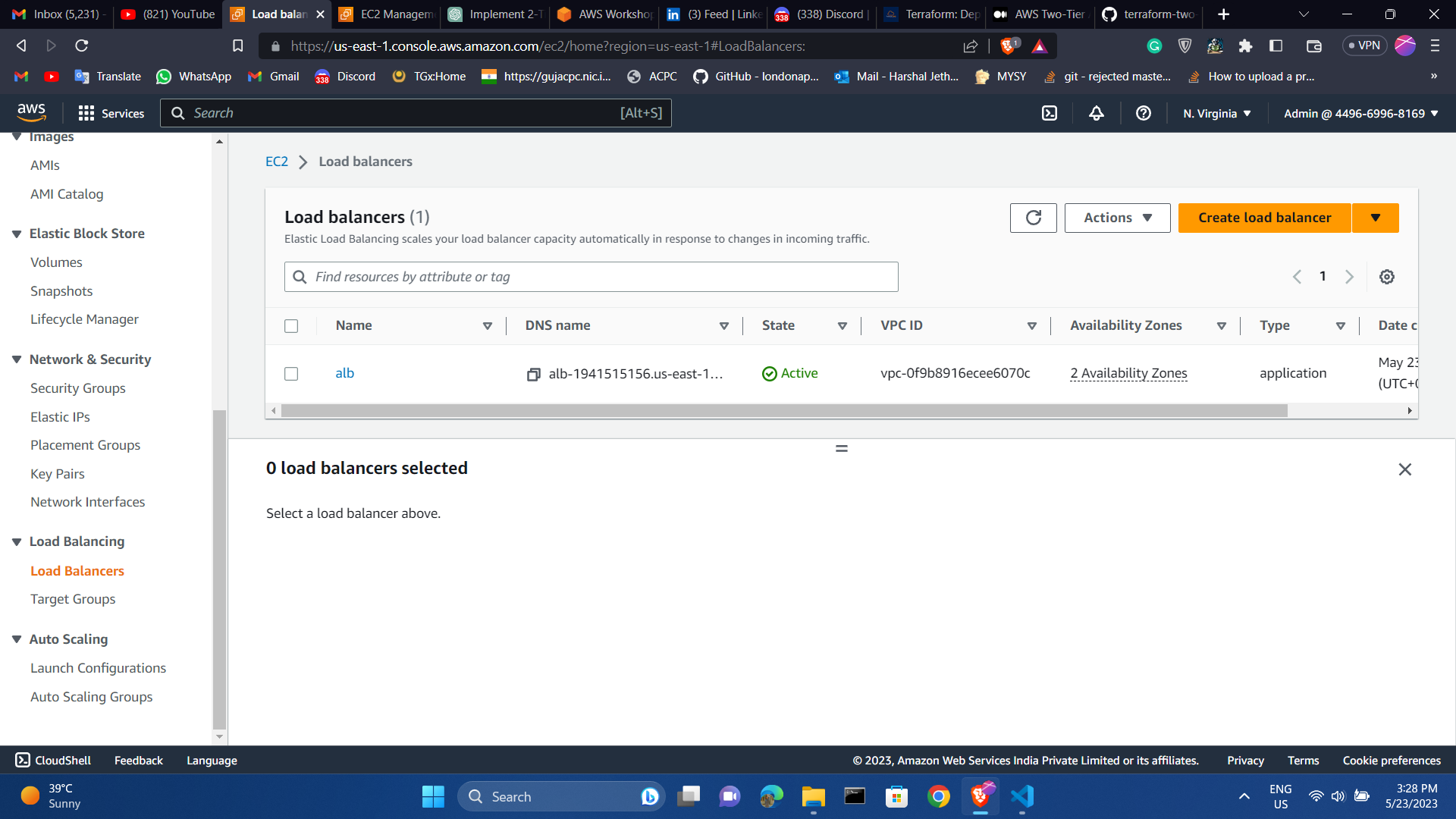
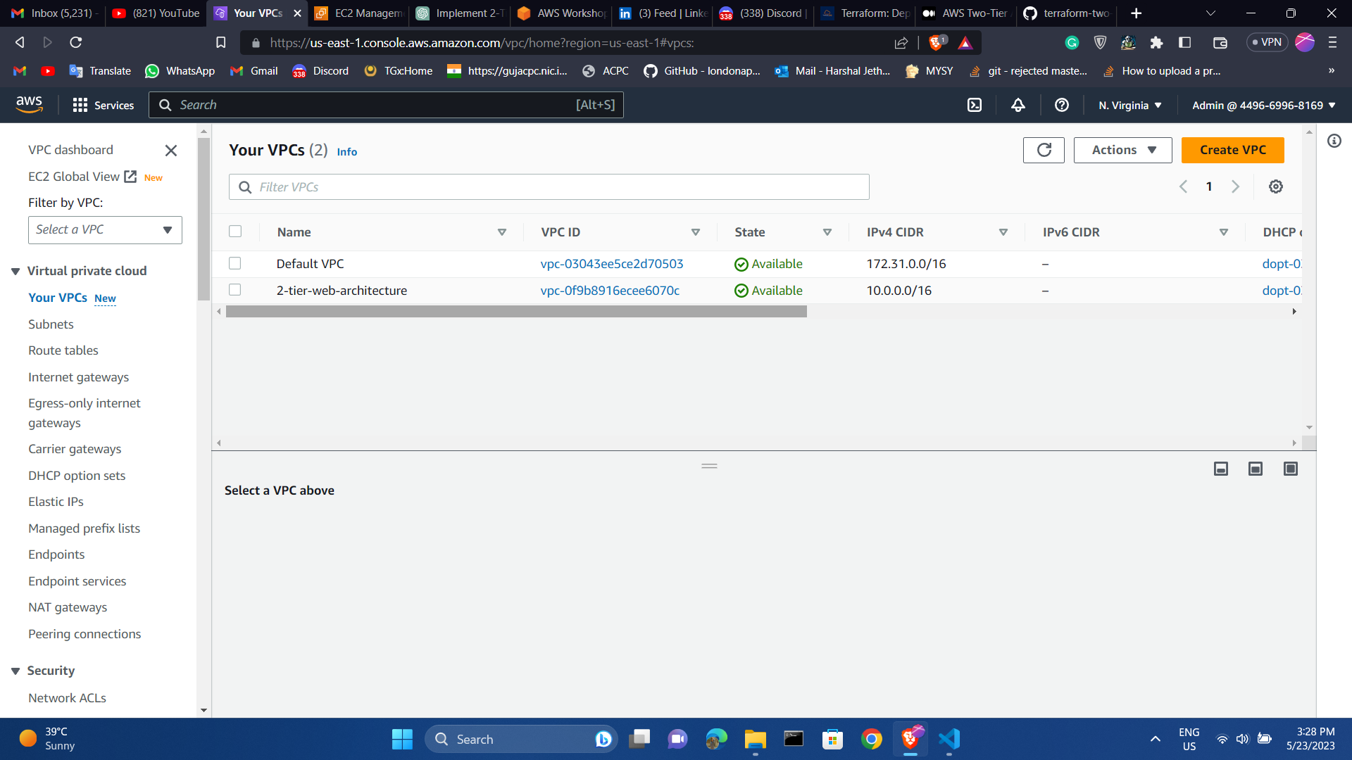
load balancer and vpc list
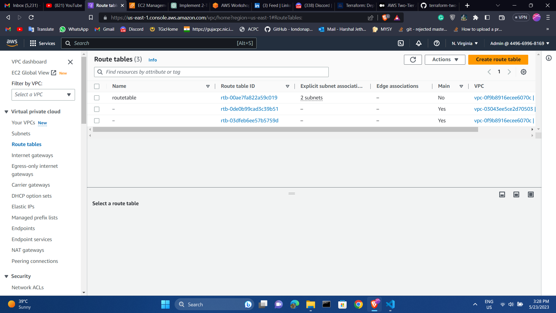
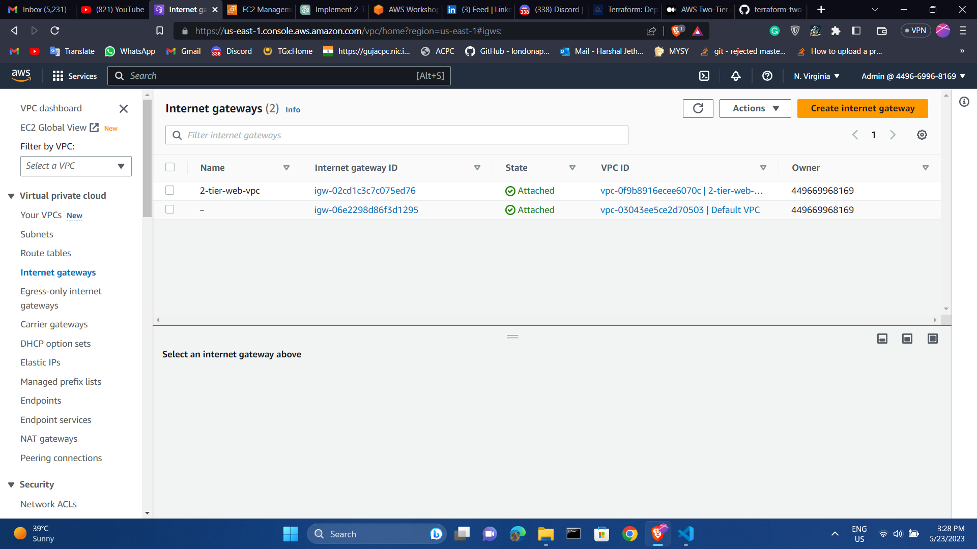
Route table and Internet gateway
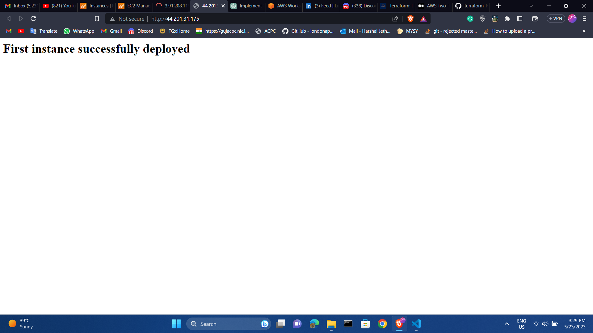
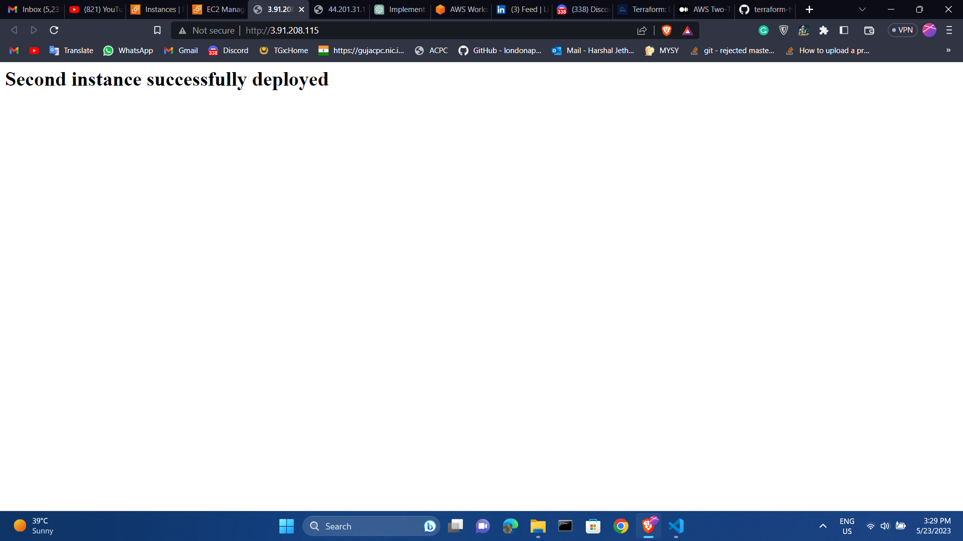
Then, the ec2 public ip url data will display :
Step 12 — Destroy Infrastructure
To initiate the deletion of the two-tier architecture, insert the following command:
NOTE:
DON’T FORGET TO DESTROY THE RESOURCES!!
terraform destroy

Follow me :
Linkedin: https://www.linkedin.com/in/harshaljethwa/
GitHub: https://github.com/HARSHALJETHWA19/
Twitter: https://twitter.com/harshaljethwaa
Thank You!!!